n.a.
| Productgroup ID | 2 |
| Packaging unit | 1 |
| Delivery information | Not assembled |
| Recommended accessories | PN kit for unlocking in the top end position |
| Required accessories | 1x BS 2 belt section or conveyor unit,2x section support SZ 2,2x 4 strut profiles 45x60,16x bracket 45x45,2x foundation bracket |
| Mandatory accessories | 1x BS 2 belt section or conveyor unit,2x section support SZ 2,2x 4 strut profiles 45x60,16x bracket 45x45,2x foundation bracket |
- Can be used for BS 2, BS 2/C-100, BS 2/R-300 belt sections and for combinations of section ST 2/C-H (ST 2/R-H), drive AS 2/C-100 (AS 2/R-300) and return unit UM 2/C-60 (UM 2/R-60)
- From width b = 240 mm to b = 1200 mm
- For passage width (A) 600 ... 1800 mm
- In open position (85°), locked
- Mechanical unlocking, optionally with pneumatic unlocking (PN-kit)
- Safety switch in off position
- Can be used as transverse section
In open position (85°), locked, Mechanical unlocking, optionally with pneumatic unlocking (PN kit), Can be used for BS 2, BS 2/C 100, BS 2/R 300 belt sections and for combinations of section ST 2/C H (ST 2/R H), drive AS 2/C 100 (AS 2/R 300) and return un
Belt section l = A + 500
Select the length (l) of the belt section (BS).
l = A + 500 mm, according to the surrounding system:
BS 2
BS 2/C-100
BS 2/R-300 plastic chain and steel chain
Conveyor unit: ST 2/R-H, AS 2/R-300, UM 2/R-60
Conveyor unit: ST 2/C-H, AS 2/C-100, UM 2/C-60
To set up a lift gate, you need:
one SZ 2 leg set with AO = profile height of one BS 2 as well as one SZ 2 leg set with parameters, see table AO = 60 mm and leg set width bSZ|
BS 2/... |
Section support SZ 21) |
Material number |
|
|
A |
b ≥ 160 MA = M |
bSZ3) = b4) + 120 AO2) = 60 mm |
3842996320 |
|
B |
b ≥ 320 MA = L; R |
bSZ3) = b4) – 120 AO2) = 60 mm |
3842996320 |
|
C |
b = 240 MA = L; R |
b3) = b4) AO2) = 60 mm |
3842996320 |
| 1) | See also support SZ 2 |
| 2) | AO = installation location |
| 3) | bsz = width b for support |
| 4) | b = width of belt section |
For A: If both plates are mounted outside of the belt section
For B: If both plates are mounted in the middle of the belt section
For C: If one plate is mounted outside or inside the belt section
Strut profile 45x60

Strut profile 45x60
CAD data
Foundation bracket

Foundation bracket
Foundation bracket for securing frames to the floor The drilled hole for the floor dowel can be made without removing the foundation bracketCAD data
Bracket 45/45

Bracket 45/45
Brackets with centering lugs for rapid, precise assembly with protection against turning Centering lugs can be easily broken off for assembly on plates or at right angles to the slot Version designLINE with special silver paint (RAL 9006) for an especially high-quality design Sliding block offset for off-center positioning of the 45/45 bracket Cover cap to protect from dirt, available in signal gray (RAL 7004) and black ESD (RAL 9005)CAD data
Belt Section BS 2

Belt Section BS 2
The belt section is a ready-to-use conveyor section with built-in drive for the transportation of workpiece pallets in the longitudinal direction or for the transverse conveying of the workpiece pallet between parallel conveyor sections in conjunction with two HQ 2 lift transverse units.Assembly instructions
CAD data
Belt Section BS 2/C-100

Belt Section BS 2/C-100
Functional operation conveyor complete with drive Longitudinal conveying of the workpiece pallet on conveyor sections of up to 6000 mmAssembly instructions
CAD data
UM 2/C-60 Return Unit

UM 2/C-60 Return Unit
Conveyor medium: flat top chain (suitable for use in an EPA) For use in conjunction with all AS 2/C-... drive modulesCAD data
Drive Module AS 2/C-100

Drive Module AS 2/C-100
Drive for conveyor unit self-assembly Conveyor medium: Flat top chain (where KA = A suitable for use in an EPA)CAD data
ST 2/C-H Section

ST 2/C-H Section
Drive for conveyor unit self-assembly For use in conjunction with AS 2/C-… drive modules and UM 2/C-… return unitsCAD data
BS 2/R-300 Belt Section

BS 2/R-300 Belt Section
Ready-for-operation conveyor section Conveyor medium: accumulation roller chain (suitable for use in an EPA) Chain tensioner for reversible operation contained in drive headAssembly instructions
CAD data
Drive Module AS 2/R-300

Drive Module AS 2/R-300
For conveyor unit self-assembly For use in conjunction with UM 2/… return units and ST 2/… sectionsCAD data
UM 2/R-60 Return Unit
UM 2/R-60 Return Unit
For conveyor unit self-assembly Conveyor medium: accumulation roller chain (suitable for use in an EPA)CAD data
ST 2/R-H Section

ST 2/R-H Section
For conveyor unit self-assembly For use in conjunction with AS 2/R-… drive modules and UM 2/R-… return unitsCAD data
Leg set SZ 2

Leg set SZ 2
Leg set for single-track conveyor sections on one conveying level. Standard versionAssembly instructions
CAD data
Floor dowel

Floor dowel
Can be used on all Ball Guide Rails SNS.CAD data
Overall width of the different lift gate assembly variants
The overall width results from the belt section width (b), the motor width (M) and other interfering contours (e.g. locking bolts for unlocking, etc.).
The requirements for other interfering contours are specified in the dimension drawings on the left.
In addition, the workpiece pallet width needs to be taken into account.
Overall width/interfering contours
|
|
Belt section |
M (mm) |
|
B |
BS 2 |
154,0 |
|
BS 2/C-100 |
158,5 |
|
|
BS 2/R-300 |
158,5 |
|
|
ST 2/C-H |
158,5 |
|
|
ST 2/R-H |
158,5 |
|
|
C |
BS 2 |
154,0 |
|
BS 2/C-100 |
158,5 |
|
|
BS 2/R-300 |
158,5 |
|
|
ST 2/C-H |
158,5 |
|
|
ST 2/R-H |
158,5 |
Interfering contours A
If both plates are mounted outside of the belt section, the minimum width of the workpiece pallet is bWT = 240 mm.
Interfering contours B
If both plates are mounted in the center of the belt section, the minimum width of the
workpiece pallet is bWT = 320 mm.
If you mount your own locking bolt or mount the PN locking mechanism, bWT = 320 mm.
Interfering contours C
If one plate is mounted outside or inside the belt section, the minimum width of the workpiece pallet is bWT = 240 mm.
Determine the LG 2/H mounting kit reference number using the tables and the description. The reference number is also the mounting kit number. This means, for example, that reference number 2 is the same as mounting kit 2.
Minimum length of the leg connection:
|
Minimum length B/C |
Connection |
|
1451) |
BS 2-Umlenkung |
|
1751) |
UM 2/C-60, UM 2/R-60 |
|
245 |
BS 2-Antrieb |
|
285 |
AS 2/C-100, AS 2/C-250, AS 2/R-300, AS 2/R-700, UM 2/C-170, UM 2/R-170 |
|
395 |
AS 2/C-400, AS 2/C-700, AS 2/R-1200, AS 2/R-220 |
| 1) | Optimum leg connection for ideal support: 220 mm |
Lift gate interfering contours
The following applies to BS 2: When MA = M and b = 160 mm, the max. permissible section load is only 30 kg

LG 2/H Mounting Kit

Note:
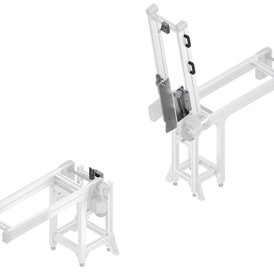
The length of the belt section (lBS) corresponds to the passage width plus 500 mm The total required space of the LG 2/H is the passage width plus 535 mmThe LG 2/H lift gate makes it possible to access or pass through the inner spaces of a belt section (BS). Manually tilting the belt section can open it from 0° to 85° or close it from 85° to 0°. The effort required to do this is reduced with the aid of a gas pressure spring.

Selection of the LG 2/H mounting kit appropriate to the belt section type

Request Quote
How to Find Us
If you have any questions, just fill in the contact form, and we will answer you shortly. If you are living nearby, come visit us.